your guide to pinball in Belgium
MPU Module
| Sympton | Cause | Procedure |
| A) Test programm of MPU does not operate, neither the game lights turn on at the playfield | a) Open fuses because of closed Zener diode. The Zener diode is closed because more than 10V has been applied at the input. | Remove fuses and check them. If they are open disconnect one of the pins of the Zener diode and with the ohmeter check if there is continuity in both senses. If it conducts in both senses, replace diodes and fuses. Check again. |
| b) +- 5V supply open or shorted | ||
| 1/ Open transistor MC150 | Checking with the test point on emitter and base, TL wil be on. Checking on collector, TL will be off. Replace MC150. | |
| 2/ Open transistor SCI48 | Checking with the test point on the base, TL will be lighted. On the emitter and base, it will not light. Replace SCI48. | |
| 3/ Closed Zener diode | TL will turn on when checking the emitter of transistor MC150 and will be off when checking the base of SC148. Replace Zener diode. | |
| B) The test programm stops at a number. | ||
| I/ Stops at 0. | a) Supply failure | With a voltimeter check if the voltage of + 5VDC,+12VDC, -5VDC on the pins of the E-PROM are correct. In the series machines, it is only necessary to have + 10VDC at pin 24, If anyone of the voltages is not correct, check the voltage at the terminals of the components and replace them if defective. |
| b) Address or data buses shorted or open. | Check with the ohmeter on the pins of the CPU if there is any line shorted to another to negative or to positive. That means: For checking the data bus put a plug of the ohmeter on pin 15 (BO) and check for continuity with the rest of the pins 8,9,10,11,12,13,14, with + and -. If in any of these measures the ohmeter shows 0 Ohms there is continuity because of a short; localize the short and repair. If the ohmeter shows a resistence but does not arrive at 0, everything is correct. The same steps are to be taken with the address bus (pins 25 to 32 of the CPU)� In this way we will see that there are no shorted buses. When checking for open circuits, with the ohmeter and MPU schedule, we must follow the trace, looking for possible shorts. Afterwards check the whole trace for continuity. | |
| c) Reset circuit or synchronization with the voltqge line. | The reset circuit actuates over pin 3 of the CPU, If we touch with the test point this pin and TL turns on, this is correct, then follow the trace and with TL see informations at the distinct control gates of this signal, A possible cause is, that transistor SC158 is closed. This can be checked easily because TL will not be on at the emitter. Replace transistor and check again. The synchronization circuit is composed by the gates of the circuit 23, pins 8,9,10 and 12,13,11. With the voltimeter check if on pins 10 and 11, 2 VDC is given. If this happens, everything is correct. If one of the pins does not have this voltage, then try to localize the failure in the integrated circuit, resistors or capacitors. | |
| 2/It stops at 1 | a) The CPU circuit does not remain connected to ROM A | Look for possible shorts between bus lines, to positive or to negative, as made for sympton Blb, Also check if there are open lines. If the above is correct, then check with the ohmeter the connections of the circuit 4042 (24) for any shorts or open lines. |
| 3/ It stops at 2 | a) The CPU circuit does not remain connected to ROM B | Look for possible shorts between the bus lines, to positive or to negative as made for sympton Bib, Also check if there are open lines. If the above is correct, then check with the ohmeter the connections of the circuit 4042 (24) for any short or open line. |
| 4/ It stops at 3. | a) The CPU does not remain connected to RAM A. | Same procedure as for last sympton |
| 5/ It stops at 4. | a) The CPU does not remain connected to RAM B. | Same procedure as for last sympton |
| 6/ It stops at 5. | a) The CPU does not remain connected to the input | Check with the voltimeter if there is no open line between the CPU circuit arid circuits 4016 (21 and 22), If the above is correct, check for continuity in the distinct outputs C1,C2,C3,C4 C5 of circuit 4028 (20), Check also if transistor SCI48 placed at the second column, is not open. |
| 7/ It stops at 6. | a) The pin 36 of the CPU does not receive signals | Check with the ohmeter if the trace between pin 36 of CPU and pin 4 of circuit 19 is correct. If this is correct, connect the machine to the voltage line arid check the voltage on pin 4 of circuit 19y which has to be 5VDC, If the voltage is different, check voltages at the input. They have to be 2VDC, If this voltage is not correct, verify resistor and capacitor. |
| C) A contact of the machine does not add points or does not do anything when touched. | a) It is always closed. | Check if the contact does not remain closed because of a incorrect regulation. Regulate it and check again. |
| b) Failure at input to MPU. | When checking with the test point at one of the contact plates, TL has to blink weakly. Then close contact and check if the signal passes to the other plate and follow the cable up to the MPU. At the same time follow the impulse over the scheme in order to know where it disappear. With this test we can localize the component, which does not allow the pass of the signal. | |
| D) One or some of the game lights do not turn on and the credit and match feature counters do not operate correctly. | a) Defective issue of the command impulse from the MP. | Localize, with the help of the letter code foreseen in each module, the defect integrated circuit. Check with the ohmeter if the input and output connections of the gates are correct, that is to say, there is no open or shorted circuit. Check also if there is continuity between MPU output and the input of the auxiliar module to verify the good contact of the connectors. |
| E) At the decoder module the input D or N are not correct. | a) Defective MPU command output. | The same procedure as for sympton D. |
| F) The coin micros do not count the correct credits. | a) Dirty credit regulation switches. | Clean with a spray the switches and let them rotate a few times. Check again. |
| G) When disconnecting the machine, it does not store the information in credit counters and players displays. | a) RAM B has no supply | With a voltimeter check the voltage at pin 18 of RAM B (33), When the machine is connected this voltage has to be 5VDC +- 0,5V. When the machine is disconnected this voltage has to remain at the same value. If this voltage falls down to zero, we have diode 1N4148 closed. Replace diode and check again. |
| H) Some game lights, the match feature or credit LEDs blink. | a) One of the transformer windings is badly soldered or shorted. | Check if the outputs lOVa, Ov and lOVb of the transformer are well soldered and there are no shorts between the terminals. |
COMPONENTS USED IN THE MPU MODULE
DIODE SY 124 (See components in thyristor module)DIODE 1N4148 (See components in decoder module)
ZENER DIODE (See components in decoder module)
TRANSISTOR SC 148 (See components in relays module)
TRANSISTOR SC 158
INTEGRATED CIRCUIT 4019 (11 and 12)
Four squares form one integrated circuit. One square is formed by:
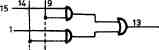 INTEGRATED CIRCUIT 4511 (See components displays module) (13)
INTEGRATED CIRCUIT 4042 (14, 17 and 24)
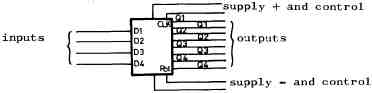
| POL | 01 | 02 | 03 | 04 | |
| 0 | 0 | D1 | D2 | D3 | |
| 0 | memorized | ||||
| 1 | 1 | D1 | D2 | D3 | |
| 1 | memorized | ||||
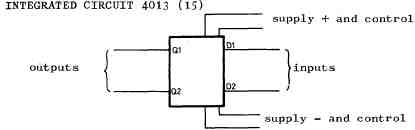
| CLK | Dl. D2. | Ql. Q2. |
| 0 | 0 | |
| 1 | 1 |
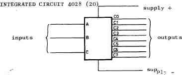
| inputs | outputs | ||||||||||
| A | B | C | C0 | C1 | C2 | C3 | C4 | C5 | C6 | C7 | |
| 0 | 0 | 0 | 1 | 0 | 0 | 0 | 0 | 0 | 0 | 0 | |
| 1 | 0 | 0 | 0 | 1 | 0 | 0 | 0 | 0 | 0 | 0 | |
| 0 | 1 | 0 | 0 | 0 | 1 | 0 | 0 | 0 | 0 | 0 | |
| 1 | 1 | 0 | 0 | 0 | 0 | 1 | 0 | 0 | 0 | 0 | |
| 0 | 0 | 1 | 0 | 0 | 0 | 0 | 1 | 0 | 0 | 0 | |
| 0 | 0 | 1 | 0 | 0 | 0 | 0 | 0 | 1 | 0 | 0 | |
| 0 | 1 | 1 | 0 | 0 | 0 | 0 | 0 | 0 | 1 | 0 | |
| 1 | 1 | 1 | 0 | 0 | 0 | 0 | 0 | 0 | 0 | 1 | |
INTEGRATED CIRCUIT 4069 (25) (See components bells module)
INTEGRATED CIRCUIT ROM A and B 1834 D (26 and 30)
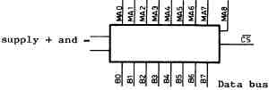
When the control signal CS falls to 0, through the 8 lines of data bus will be given the information corresponding to the adress which at the moment is in the adress bus.
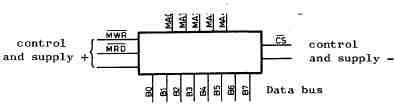
INTEGRATED CIRCUIT RAM A and B 1824 D (27 and 33)
When the control signal CS gets negative, there are two possibilities:
MWR=0 and MRD=1 - In this case the information which is in the data bus will be written in the RAM circuit at the adress indicated by the address bus.
MWR=1 and MRD=0 - In this case the information in the address shown by the address bus, will be leaving through the data bus.
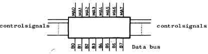
INTEGRATED CIRCUIT CPU 1802 D (28)
Controls the rest of the circuits of the machine. Its function is quite complex. When the input CLEAR becomes 0; the CPU is set to 0,
When giving 1 again, the address bus starts to count. It starts with 000,000, then 000,001 and so on.
PARTS OF THE MODULE M.P.U.
| Description | Quantity |
| Integrated circuit CD4013AE | 1 |
| " " CD40Q1AE | 1 |
| " " CD4011AE | 3 |
| " " MC4016CP | 2 |
| " " CD4019AE | 2 |
| " " CD4023AE | 1 |
| " " CD4028AE | 1 |
| " " CD4042AE | 3 |
| " " CD4069BE | 1 |
| " " CD4072BE | 1 |
| " " CD4075BE | 2 |
| " " CD4081BE | 8 |
| " " CD4511BE | 1 |
| " " CPU CDP 1802 D | 1 |
| " " RAM CDP 1824 D | 2 |
| " " ROM CDP 1834 D | 2 |
| Transistor SC158 | 1 |
| " MC 140 | 1 |
| " SCI 48 | 1 |
| Diode SY124 | 4 |
| " 1N4148 | 5 |
| " 11V 400mW ZENER | 1 |
| " 15V 400mW " | 1 |
| Sliding switch 2x1 | 2 |
| Fuse� holder | 4 |
| Fuse 1A | 2 |
| Pin Comboline | 86 |
| Rivets printed circuit | 370 |
| Metal plate M.P.U. | 1 |
| Switch button | 2 |
| Rotative switch 8x1 | 2 |
| Printed circuit M.P.U. ref. 510049 | 1 |
| Socle 40 pins | 1 |
| " 24 pins | 1 |
| Radiator | 1 |
| Dividers 10 mm | 9 |
| Screw 1/8 x 5 | 9 |
| Nut 1/8 AD-2 | 9 |
| Resistor 100 1/4W 10% | 1 |
| " 390 1/4W 10% | 7 |
| " 470 1/4W 10% | 1 |
| " 1K 1/4W 10% | 14 |
| Resistence 4K7W 1/4 10% | 4 |
| " 10K 1/4W 10% | 89 |
| " 100K 1/4W 10% | 22 |
| " 470K 1/4W 10% | 2 |
| " 1M 1/4W 10% | 1 |
| Condenser 82 pF ceramic | 1 |
| " 1K " | 8 |
| " 10K " | 5 |
| " MKM 0,01 uF 250V | 2 |
| " MKM 0,22 uF 10CV | 1 |
| " MKM 0,47 uF 100V | 1 |
| " electrolitic 220 uF l6V radial | 1 |
| " " 1100 uF 16V axial | 2 |
CODE OF THE MODULES
In all modules, close to the pins, there is a printed code number. The same code number is used to indicate the output pin of a module and the one corresponding to the input of another module. Each codification defines a specific function and therefore there are not two different functions with the same code number, except the two cases as detailed below:1.� Relation between input code of the thyristor module and the corresponding outputs of MPU module.
| Code Thyristor | Code MPU |
| T1 | W7 |
| T2 | U7 |
| T3 | U6 |
| T4 | U5 |
| T5 | U4 |
| T6 | U3 |
| T7 | U2 |
| T8 | U1 |
| T9 | V8 |
| T10 | V7 |
| T11 | V6 |
| T12 | V5 |
| T13 | V4 |
| T14 | V3 |
| T15 | V2 |
| T16 | V1 |
| T17 | -- |
| T18 | W4 |
| T19 | W3 |
| T20 | W2 |
| T21 | W1 |
| T22 | W8 |
| T23 | W6 |
| T24 | W5 |
2.- Relation between input code of Displays modules and corresponding outputs of Decoder module. See in code diagram the indication corresponding to the pins of the connectos numbers 8-7-6 and 5 of the Decoder module with the ones corresponding to the Displays.