your guide to pinball in Belgium
Introduction
The machine "BIG TOWN", Solid State System has been designed employing the new technique of MICROPROCESSORS. Such a system has numberless advantages as: high reliability, absence of interferences and spectacular reduction of necessary components. All that reduces infinitely the failure probability.
For more versatility, easy failure and common stock pieces location in the distinct models of machines the electronic circuits unit has been divided into different modules:
| 1. | RELAYS MODULE |
| Its function consists in driving current to the distinct electromagnets necessary for the play and cutting the current to these electromagnets in case of Tilt or Game Over. | |
| 2. | TARGET RELAY |
| Its function consists in raising the targets. | |
| 3. | THYRISTOR MODULE |
| Its function consists in controlling the different lights that are to be lighted during the play. | |
| 4. | BELLS MODULE |
| Its function is transforming and amplifying some voltage impulses to the different frequencies that are characteristic for each note. | |
| 5. | DISPLAYS MODULE |
| Has as function to visualize in digital form the score of the players. | |
| 6. | DECODER MODULE |
| Its work consists in helping the MPU module to control balls, cone, displays and relays module. | |
| 7. | CREDIT AND MATCH FEATURE MODULE |
| Has as function to visualize, in digital form, the credit and match feature. | |
| 8. | MPU MODULE |
| Its work consists in receiving information from the different contacts of the machine, processing this information and using it to govern the distinct modules. |
GENERAL INSTRUCTIONS
When you receive the machine, or, after a long time (two months), without using it, and you connect the machine, it is possible that some numbers of the displays do not turn on and that the credit shows a number different from zero. You must make the necessary adjustments in order to put the machine ready for playing and the problem will be solved.
All the MPU inputs and outputs have voltages around 5V, but at very high frequencies. Because of that, it is impossible to measure them with a normal voltimeter.
All the wires that go in and out the MPU have a series resistors to limit the maximum shortcircuit current.
Due to the small intensity that goes through the wires going in and out the MPU, it can be derived to ground through the human body when touching a wire. It is absolutely normal and it does not affect the normal operation of the machine.
For better operation of the electronic part of the machine a special and independent winding has been made in the supply transformer. Try, naturally, to avoid shortcircuits with any other winding.
Be always sure not to apply more than the correct voltage to MPU, If higher voltage is applied, an internal protection circuit will operate blocking the machine. The symptons that will be produced are: none of the lights will turn on, the digital counters for credit and match feature will be off and the displays will keep the same scores with out appearing the SCORE TO DAY.
The 3 Amp.fuses, that feed the lamps, have been calibrated to blow in case of shortcircuit in a lamp socket. So, do not use fuses of a higher value, since the diode and the thyristor could get damaged, instead of blown the fuses.
All the contacts that are placed on the playfield, form a matrix. Due to this configuration, there are five common conductors and always only one of them will have current. First conductor A, afterwards B, then C, D and finally E, And the cycle will be repeated.
When the machine is in Game Over, the cycle will be between A and B. At the beginning of the play the whole cycle will occur.
With this matrix location, it is easy for MPU to know which is the closed contact, since MPU knows which column, by the moment, has current and also trhough which input returns the current. If anyone of the contacts remain closed, MPU is programmed to overlook it and to act as if that contact were always open.
The information, which is visualized on the displays, is refreshed 30 times in a minute, because it could be lost due to the interferences. This is the reason why we will see the test lamp blinking, when we test the command signals L1 to L8 with the test point.
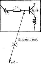
For checking and in case of failure, it is possible to make bridges to positive or to negative. It is important, when making these bridges, not to make them directly from the inputs or the outputs of an integrated circuit or from the base of a transistor, but always through a resistor, that normally is connected to them.
Example:
 correct
IMPORTANT REMARK
In the preseries the memories used are EPROM. For supply they need special voltages: +5 VDC +- 0'5 V at pins 24 (This is the same voltage supply for the integrated circuits placed in the module), +12 VDC +- 0,5 V at pins 19; -5 VDC + 0,5 V at pins 21.In the series the memories will be ROM and for them no special voltage supply is needed. In these machines the supply voltage will be + 10 VDC +-0,5 V, just the same as the voltage used for integrated circuits. In these machines the components used for the special voltages will be supressed.
The troubleshootings in the MPU module are explained for the preseries machines, that means, with voltages + 5V,+12V and - 5V. For the rest of the series it will be easy the interpretation by changing + 5V by + 10V.
In the DECODER module and for the preseries there have been used integrated circuits LM 324, whose function is to raise the voltage level from 5 volts coming from MPU to 10 volts which is the voltage of duty at DECODER module. When the memories are ROM all these circuits will disappear since the duty voltages in MPU and DECODER module are the same.
GAME ADJUSTMENTS
At the moment of connecting the machine to the voltage line, at the credit and match feature counters, the numbers 1 to 6 will appear. These numbers correspond to the test which verifies the MPU module. When the machine is at the Game Over state, there is a continous movement of the lights on the board. It is at this moment that the adjust or control push buttons, as described below, can be operated.
| 1. | Push-button 1 M (Located at the coin door) |
| When pushed, the number of coins, that have passed through the first coin selector, is visualized at the first player display. After two seconds this in formation is erased although the button is still pushed. To visualize the number of coins again, it is necessary to push the button once more. | |
| 2. | Push�button 2 M (Located at the coin door) |
| When pushed, the number of coins, that have passed through the second coin selector is visualized at the first player display. After two seconds this in formation is erased although the button is still pushed. To visualize the number of coins again, it is necessary to push the button again. | |
| 3. | Push-button 3 M (Placed at the coin door) |
| When pushed, the number of coins, that have passed through the third coin selector is visualized at the first player display. After two seconds this in formation is erased although the button is still pushed. To visualize the number of coins again, it is necessary to push the button once more. | |
| 4. | Push-button Credit by coins (Placed at the coin door) |
| When pushed, the total number of coins by credit, that have passed through any of the coin selector, is visualized at the first player display. After two se conds this information is erased although the button is still pushed. To visualize the number again, it is necessary to push the button once more. | |
| 5. | Push�button Credit by Awards. (Placed at the coin door) |
| When pushed the credit, that the players have reached by Special, points, "Score to date" and Match Feature is visualized at the fist player display. After two seconds this information is erased although the button is still pushed* To visualize this number again, it is necessary to push the button onece more. | |
| 6. | Push-button first credit by score (points), (Placed at the coin door), |
| When pushed, it is visualized at the first player display at which score will be given the first credit. If the button continues pushed, after two seconds, the score will begin to raise by adding 10,000 points each two seconds. When the desired score is reached, leave the button free. If not desired to give any credit by score, set the score to 000,000, | |
| 7. | Push�button second credit by score (placed at the coin door). |
| When pushed, at the first player display is visualized at which score will be given the second credit. If the button continues pushed, after two seconds the score will begin to raise by adding 10,000 points each two seconds. When the desired score is reached, leave the button free. If desired not to give any credit by score, set the score to 000,000 | |
| 8. | Push�button third credit by score (Placed at the coin door) |
| When pushed, at the first player display is visualized at which score will be given the third credit. If the button cintinues pushed, after two seconds, the score will begin to raise by adding 10,000 points each two seconds. When the desired score is reached, leave the button free. If desired not to give a third credit by score, set the score to 000,000 | |
| 9. | Push�button Score to Date, (Placed at the coin door) |
| When pushed, the score at which the "Score to Date"
is regulated, falls down instantaneously to 500,000
points in order to allow to put the "Score to Date"s
score at a quantity less than the one obtained by the
players. If the button continues pushed, after two
seconds the score will begin to raise by adding 10,000
points. When the desired score is reached, leave the
button free. The award of Score to Date is given by
the machine when surpassing in 100, 1000, or 10,000
points the established score and once obtained follows
the score of the player who it has obtained.
When a player reaches the "Score to Date"s score the machine will give him 3 credits, a special music will sound and a frontal light, showing "Score to Date" will turn on. This light will remain on during the whole game indicating in this way that one player has sur passed the highest score and if another player wants to obtain the award of the "Score to Date", he should beat him. If desired to disable the "Score to Date" award, it is enough to set the score to 000,000. In case a player should surpass the quantity of 999.000 points, the machine remains automatically regulated at 999.000 points, independently of the score he should surpass. | |
| 10. | Push-button Test (Placed at the coin door) |
It is used to verify the correct operation of the
machine.
When the push-button is pushed, it works as explained below:
| |
| Switch 5 ball - 3 balls (Placed in the M.P.U. Module light box) . | |
| In a match 3 or 5 balls will be available depending on the state of the switch. | |
| Switch EXTRA BALL - GAME (placed in the light box, moduleM.P.U.) | |
| In Game position, the credit counter will add the credits
obtained through Specials, Score, Score to Date and Match features. In EXTRA�BALL position, an extra ball will be available, when during the game Specials, Score awards or Score to Date awards have been obtained. In this positions the match feature is cancelled. | |
| Switch second selector (Placed in the light box, module M.P.U.). | |
| With this conmutator, the number of credits which the
second coin selector will produce, when putting a coin
can be regulated. The available positions are: 1/2, 1, 3/2, 2, 3, 4, 5, 6 credits. If we have the switch in the 1/2 position and introduce a coin, no credit will be given, but introducing a second coin a credit will appear at the counter. If we have the switch in the 3"3 position and introduce a coin, one credit will appear at the credit counter and 1/2 credit will be memorized waiting for the second coin. If in this moment we set the machine in play, the half credit will be kept until Game Over and at this moment this half credit will be cancelled. | |
| Switch third selector (Placed in the light box, M.P.U. module) . | |
| With this switch can be regulated the number of cre dits the third selector will give when introducing a coin.
The available positions are: 3,4,5,6,7,8,9 and 10
credits. In the machines, which have installed three selectors, the first selector always gives only one credit. | |
| 11. | Push�button Reset. (Placed at the light box) |
| When pushing this button, the information contained in memories of push-buttons 1,2,3,4 and 5 is set to zero. It also sets to zero the credit counter. |