your guide to pinball in Belgium
DETAIL OF THE ELECTRONIC COMPONENTS USED IN THIS MACHINE
| 1. | Test voltages with the voltimeter |
| Having this instrument, it will be set to read continuous or alternated voltage depending on the kind of voltage we need to measure. The negative plug of the voltmeter will be connected to the negative pift of the MPU and with the positive plug the different points will be checked. | |
| 2. | Continuity test with ohmeter |
| For this test, it is necessary to disconnect the machine from the voltage line. Once the machine is disconnected, continuity can be checked between the desired points. | |
| 3. | Test if TL (Test Lamp) gets lighted |
| In the DECODER module a little lamp has been incorporated. This little lamp gets lighted with voltages of 2,5 V. To check if there is enough voltage in a certain point, just touch the point with the incoporated plug. |
RESISTOR
It is a component that offers a resistance or difficulty to the pass of the current. Its function in the machine is to create a voltage drop (Bumper lights) and to limitate the current, that flows to a certain component, (Thyristor, transistor ,..).CAPACITOR
It is a component which stores an electrical charge and supplies this charge, when the voltage, which has produced this accumulation disappears. Its function in the machine is to provide pure continuous voltage (electrolitics) and eliminate the parasites produced in the alternated current.DIODE
It is a component that only allows the pass of the current in one sense. When the anode is positive and the cathode more positive, the diode behaves as an open circuit, but if the cathode is more negative the diode behaves as a short circuit, (See fig.l)TRANSISTOR
The function of the transistor in these machines is called switching. (See Fig. 2)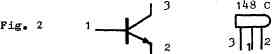 Pin 2 (emitter) is connected to the negative. Pin 3 (collector) is connected to the positive through a
load (ex. coil relay). When we apply a positive current to the base (pin l), the transistor will
switch, remaining joined electrically pins 2 and 3.
Pin 2 (emitter) is connected to the negative. Pin 3 (collector) is connected to the positive through a
load (ex. coil relay). When we apply a positive current to the base (pin l), the transistor will
switch, remaining joined electrically pins 2 and 3.In this way we have the load between the positive and negative potential. When the current at pin 1 stops the transistor will be opened, leaving an open circuit for the negative potential, (See fig.4)
THYRISTOR
It is a controlled diode. Pin 2 (cathode) is connected to the negative potential. If we apply a potential of 1 volt with a current of 1 Ma. (0.001 A.) to pin 1 (gate), the diode will allow the pass of current, if pin 3 (anode) is positive. When the voltage in pin 3 becomes negative, the diode will stop conducting if the voltage in pin 1 has disappeared (See fig. 3).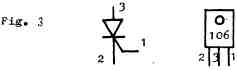 For easy comprension we can find for the transistor as well as for the thyristor a resemblance with an electro
magnetic relay of an open contact, (see fig,4)
For easy comprension we can find for the transistor as well as for the thyristor a resemblance with an electro
magnetic relay of an open contact, (see fig,4)
 We connect coil terminal 2 to 0V voltage arid also one of the little plates of the contact.
Through the coil terminal 1 we apply an impulse which necessarily has to be positive.
At this moment the relay remains activated, closing the contact which passes the negative potential 0V to the plate of contact 3.
We connect coil terminal 2 to 0V voltage arid also one of the little plates of the contact.
Through the coil terminal 1 we apply an impulse which necessarily has to be positive.
At this moment the relay remains activated, closing the contact which passes the negative potential 0V to the plate of contact 3.
INTEGRATED CIRCUITS
Due to the great number of electronic components (resistors, transistors, diodes...) employed in these integrated circuits, some defining symbols are used.In this handbook the used integrated circuits are explained, but it is important to have a previous knowledge of some necessary details of its operation.
| 1. | Low state "0" It is defined when we have 0 volts |
| 2. | High state "1" It is defined when there is supply voltage in a point. It will be 5V in the MPU and 10V in the Decoder. |
| 3. | BUS It is used in the MPU module and defines a group of strips or cables which can be used by any of the modules connected to it. |
| 4. | How the pins are numbered. Three practical examples of the numeration of pins 14, 16 and 24. (See fig.below) |
 For representing the integrated circuits, two different methods are used. One consists in representing
them with a symbol when they are simple circuits such as logical gates. In that case an integrated circuit
can be composed of 2 to 4 gates. The other method consists in representing the integrated circuits (IC)
with a rectangle. This method is used when the IC is complex.
Representation with symbols:
For representing the integrated circuits, two different methods are used. One consists in representing
them with a symbol when they are simple circuits such as logical gates. In that case an integrated circuit
can be composed of 2 to 4 gates. The other method consists in representing the integrated circuits (IC)
with a rectangle. This method is used when the IC is complex.
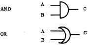
Representation with symbols:AND GATES - when a and b are 1; c will be 1
OR GATES - when a or b is 1, c will be 1
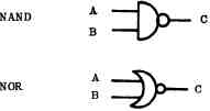
NAND GATES - when a and b are 1 then c will be 0
If one of the inputs (a or b) is 0 then c will be 1
NOR GATES - when a and b are 0 then c will be 1
If one of the inputs (a or b)is 1 then c will be 0
(See fig. below)
 Representation with rectangles
(See Fig. below)
Representation with rectangles
(See Fig. below)
 NOTE: After the troubleshooting methods of each module
the function of the complex circuits is detailed.
NOTE: After the troubleshooting methods of each module
the function of the complex circuits is detailed.
TRANSFORMERS
The primary of the main transformer is connected to the voltage through a fuse of 6A and has different inputs to be regulated according to the voltage line in each case.The primary of the auxiliar transformer and the primary of the main transformer are joined in the 0-110V.
The secondaries of the main transformer are 0-7V, which are used to feed the lamp bulbs of the fixed lights. 0-28-30-33V, used to feed the electromagnet coils, whether in alternated current (direct from the transformer), in the case of the taca, ball dispenser, up-down targets, or through a rectifier bridge, which transforms the alternated current in continuous current, in the case of the flipper, bumpers and kickers. The secondary of the auxiliar transformer is 10-0-10V. Its use in the machine is to feed the different electronic modules and the different lamp bulbs used during the game.
Something to emphasize for the comprehension of the thyristor function, are the waveshapes, which are present
in each one of the three points. (See fig.5).
 We will observe the waveshapes of a potential with regard to
another. From 10Va to 0V and from 0V to 10 Vb.
When the lOVa point has the positive half wave, the 0V point has a negative half wave with regard
to the lOVa potential; but positive with regard to the lOVb potential, which at this moment has a
negative half wave. (T1). Therefore, when the 10 Va has the negative half wave, the 0V point has a positive half wave,
with regard to the lOVa potential, but negative with regard to the lOVb potential, which at the moment has a positive half wave. (T 2).
We will observe the waveshapes of a potential with regard to
another. From 10Va to 0V and from 0V to 10 Vb.
When the lOVa point has the positive half wave, the 0V point has a negative half wave with regard
to the lOVa potential; but positive with regard to the lOVb potential, which at this moment has a
negative half wave. (T1). Therefore, when the 10 Va has the negative half wave, the 0V point has a positive half wave,
with regard to the lOVa potential, but negative with regard to the lOVb potential, which at the moment has a positive half wave. (T 2).