
How electronic pinball machines work: Understanding the circuits
This article explains how electronic pinball machines operate, excluding pre-1977 electromechanical models. The fundamental principles remain consistent across all brands and generations. While implementations may vary, some machines split circuits across multiple PCBs, others combine them, modern games typically feature additional boards and functionalities. As technology evolved, more features became possible, but the core functions are still present in every pinball machine.
Note: There may be exceptions to some of the points discussed. Occasionally, a specific manufacturer may deviate from the norm for a few models. My goal is to provide a general understanding of how pinball machines work, rather than catalog every exception.
When I refer to circuits, I mean electronically distinct systems. You can also think of them as separate functions, tasks, or areas. A basic understanding of electronics is essential, especially if you plan to perform your own repairs.
Electro-mechanical games do have some components in common, but they may look different. They don't have a matrix for switches or lights. Each switch and light bulb is individually controlled via a dedicated set of wires. The control of all parts is not done by a computer like we know it now, but the logic is implemented as a mechanical computer, using motors and switches.
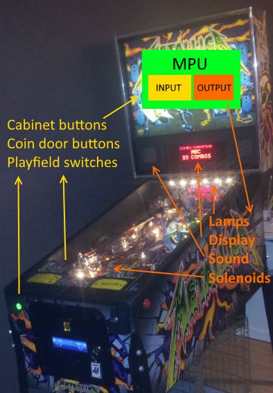
The easiest way to explain how a pinball machine works, is to compare it with a computer. There is a computer inside, after all. There's the computer board and everything associated with it (like a power supply). A computer accepts input. On a laptop you press keys on the keyboard. On a pinball machine, a player presses the buttons on the cabinet, and the pinball activates switches on the playfield. The computer sees these switch closures as input, and will react on them. The output of the computer is not just something displayed a screen or a sound, but also mechanically. The computer in the pinball machine can activate light bulbs and coils. Coils are the parts that have an impact on the ball and affect its path.
Basic circuits in a pinball machine
- Transformer
- Power Supply / Voltage Regulation
- CPU
- General Illumination
- Solenoid Driver
- Lamp Driver
- Sound Circuit
- Score Display
- Switch Matrix
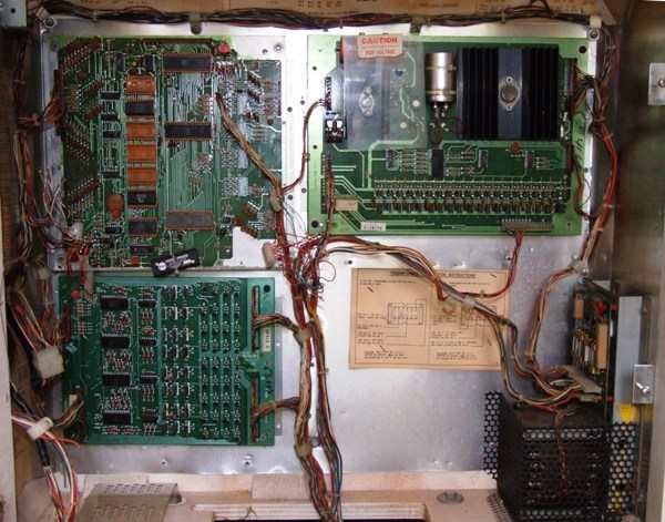
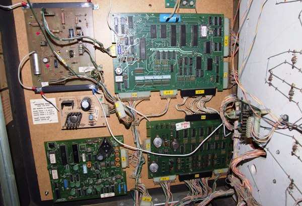
Standard backbox configuration of first generation Bally electronic games.
Top left: cpu board. Bottom left: lamp driver. Top right: solenoid driver board + display high voltage.
Bottom right: transformer with power board above it.
Transformer
Every pinball machine includes a transformer that converts AC wall voltage into usable AC voltages for the machine. I consider this circuit to encompass everything from the wall plug to the transformer's output. Essentially, all components operating on wall voltage (110V or 220V). This includes fuses, on/off switches, line filters, and surge protection.
When lightning strikes, these components often absorb the damage, protecting the rest of the machine. Typically, this entire circuit is located in the bottom cabinet. Only a few early Stern/Bally games placed the transformer in the lower right side of the backbox. Stern Spike machines also have a power supply in the bottom right of the backbox, close to their on/off switch.
Important: Always unplug the machine from the wall before working on this circuit. For other circuits, it's safer to leave the machine switched off but plugged in to maintain a ground connection.
See this article on pinball machines tripping house breakers for visuals of line filters, fuses, and surge protection on Williams WPC games.
Power supply / voltage regulation
This circuit converts the AC voltage from the transformer into regulated DC voltages. Usually housed on a single board, it may be distributed across multiple boards if specific voltages are needed for components like sound or score displays.
Newer games use a computer-style power supply.
AC power from the transformer is unregulated and fluctuates. For example, coils rated at 50V may show up to 70V on a digital multimeter when idle. Wall voltage itself isn't exactly 110V, it varies within a range.
Regulated power is essential. The CPU board, for instance, requires exactly +5VDC. Any fluctuation, especially a drop, can cause malfunctions or a reset of the game. Bridge rectifiers convert AC to DC, capacitors smooth the output, and other components like transistors adjust voltages as needed. Boards with this function often include fuses, test points, and LEDs to verify voltage presence.
Typical outputs include +5VDC for logic boards, high voltages for score displays, and 12V or 20V for sound boards. Motors and special circuits may have their own voltage regulation systems.
CPU - Central Processing Unit
Or the MPU, Main Processing Unit, is usually located on a dedicated PCB. It's the brain of the pinball machine which controls everything. Once booted, it controls lamps, solenoids, sounds, score displays, and responds to switch inputs (from the playfield or cabinet) with corresponding outputs. Some newer games have an actual computer motherboard in them, and not something the manufacturer custom made.
If the CPU fails, the game won't start or may behave erratically. The board includes a reset function, a processor chip, EPROMs with game-specific instructions, and memory chips for temporary data storage.
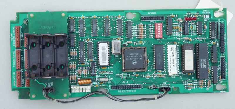
A-17651 Williams WPC-S security cpu board.
The largest IC (in a socket) is the processor. To its left (with a label) is an EPROM which containts the game rules. The switch matrix section is located beneath the battery holder (left side of photo). (Photo by Erik)
General illumination
GI is a circuit that provides power (usually around 6VAC) to the lightbulbs on the playfield and backbox that do not serve any function but to provide additional light on the game. They are just there so the game is not dark - this in contrast to lightbulbs that are controlled by the cpu and can be switched on and off individually and have as task to indicate something to players (more on these later).
Usually there are multiple strings (everything on one wire would put too much load on the circuit / connectors).
On older games they are directly connected to the output of the transformer. You could compare these to a string of Christmas lights.
So if you plug in a pinball machines and lights on the playfield work, it just indicates the transformer is working and the main fuse hasn't blown..
it doesn't mean you can play ! (as you need a working cpu for that).
On more modern games the cpu has some control over the GI. They are split up in a few strings (ie backbox, lower, middle and top of the playfield), and the cpu can control them: turn a string off, on, or set a specific brightness levels.
Some manufacturers of newer games don't have GI circuits anymore. All the lamps on the game are individually controlled and sometimes are multi-color.

Only static lights, no blinking lights, nothing on the score displays ?
It's dead Jim..
Solenoid driver
This circuit takes output from the cpu and activates coils. It consists mostly of transistors and related components (resistors and diodes), a few ICs to interpret the signals from the cpu. The circuit to drive flashlamps can be included in this, as it is in function very closely related to that of the solenoids, and on some brands the circuits are combined.
Strictly speaking, providing power to the solenoids is not part of this circuit (it's part the power circuit).
On every electronic pinball machine, power is always present at the coils. The transistors on the solenoid driver board do not switch power on/off to specific coils,
but complete the path to ground to activate a coil. It's a subtle difference, but an important one when troubleshooting or trying to understand how the machine operates.
Usually there's a high and low power part. Some strong coils require a lot of power (up to 70 volts), and to handle this, a setup involving multiple transistors exists. Other coils, motors, work on a lower voltage. To drive these a slightly different type of circuit (involving less or other transistors) is used.
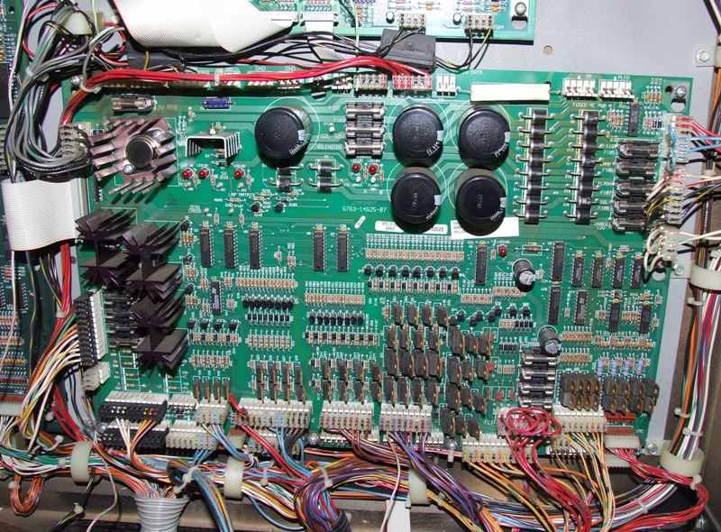
A-20028 WPC-95 power driver board. Most of the top half is the power part (fuses, thick diodes, black round capacitors), they smooth the voltage, change it into DC, ..
On the left are parts mounted on heath sinks, these are to dim the general illumination.
All the transistors at the bottom part are for lamps and solenoids.
Lamp driver
The lamp driver board is similar in function to the solenoid driver board: it allows the cpu to control specific lamps. That's the difference with GI lamps - controlled lamps can be individually switched on or off. Another difference is that controlled lamps have DC power, not AC. It's a small but important difference, you have to know on what setting to use on your DMM when you want to measure voltage on lamps on the playfield, as physically all lamps look the same.
Similar to the solenoid driver board, controlling lamps is done using transistors (or comparable parts like triacs). There is one important difference - while each coil is driven by an individual transistor, lamps are connected in a matrix.
As there can be many lamps on a pinball playfield, wiring each lamp individually would not be easy. For each lamp you'd need a wire, which going back to a connector
on the board, and an individual transistor.
Because the voltages are low, a lamp matrix could be implemented to simplify this. Think of a chess board with 8 rows and 8 colomns. Each of the squares is a lightbulb.
They are all connected using 16 wires: 8 for the rows, each wire goes from each lamp in the row to the next in that row. 8 column wires, also each one goes from the
first lamp in the column to the next. So only 16 wires and transistors are needed to control 64 bulbs.
To light specific bulbs, the cpu activates the first row. Then it'll activate the rows for the lightbulbs that need to be lit in that first row.
Those bulbs will light as both wires they have (row and column) get power.
Then the cpu deactivates the first row and does the same for the second, and so on. For each row the correct columns are switched on.
This process goes very quick. As filaments in lightbulbs do not immediately dim when power is cut, it looks to us like the lightbulbs are constant on,
while in reality they are turned on and off very quickly.
Sound circuit
There's not much to say about the sound circuit. It's an individual circuit that gets input from the cpu. Usually the input is limited (ie. play sound 1, 2, 3, ..). The sound circuit gets this input and does what's asked from it: play the specific sound.
This circuit also consists of different parts. One part is to process the input from the cpu. Another part generates the sound (this can be a simple sound generator chip, or eproms that contain specific sound samples). Lastly there's an amplifier part (which usually needs its own specific voltages) and the output of this sent connected to speakers.
Gottlieb Haunted House backbox.
Top left: power board. Top right: CPU.
Bottom right: Lamp + solenoid driver board.
Bottom left: sound board. Middle left: extra power board for sound board.
Far right center : extra lamp driver board.
Score display
The score display circuit is similar to the sound circuit. It's again a dedicated part that takes output from the cpu and does something with it. In its simplest form it'll do just show the score on a numeric display, but it can be more complicated things like show an animation on a dmd (and the animations are stored in eproms on the display driver board), and on newer games it's just a computer screen that displays animations.

Dot matrix display can show scores, text and animations.
Switch matrix
This is usually not considered to be a dedicated circuit, as it's mainly part of the cpu board. But as it's very similar to the lamp driver board I prefer to list it separate.
Most types of pinball machines have two types of input switches: direct and matrix.
The number of direct switches is usually limited (ie the service switches inside the coin door) and are connected individually to the cpu.
Most other switches on the playfield are hooked up in a matrix. Again like our lamp matrix, we have 8 wires for each row, and 8 wires for each column.
That way 64 switches can be connected to the cpu.
Operation is similar to the lamp matrix: the cpu sends a signal on the first row and checks on what columns it gets something back. Then it knows what switches are closed.
Then it sends a signal on the next row and again reads all columns, now it knows what switches in that column are closed. And so on, all the time, very quick so no
switch closures are missed.
Here's more information about how the switch matrix works on WPC games.
Conclusion
Now what is the goal of this article ? First it is to give you an overview of how a pinball machine works and what parts are involved. Try to identify the tasks of the boards in your pinball machine.
Second, if you ever have to troubleshoot a problem, knowing the circuits involved is very important.
For almost each one (sounds, displays, lamps, coils, ..)
there are self-tests that you can run. With these you can to try and diagnose problems.
Each of these subsystems usually is split out is the schematics from another circuit.
So it helps to know what page you need to look at and what components are involved, and how they work together.
If you're looking for pinball parts, then check out Pinballshop.nl (affiliate link).