
Switch on the service plug together with your pinball machine.
As written in my service plug article, inside in the cabinet of a WPC pinball machine
there's a plug that you can use for a soldering iron. It's useful, as it always has power, even when the machine is
switched off.
Sometimes however you want to this plug to only have power when the pinball machine is switched on.
I've recently installed an extra amplifier on my Attack from Mars pinball machine, and don't want to turn it off seperate.
Nowadays more and more people start to mod their pinball machines, and also add extra lights. Then it's very useful
to be able to power them all from within the game, and have them go on and off together with it.
It's not very useful to do, I re-use the parts I cut, and only need 4 connectors. You could also nicely solder them
and use shrinktube.
This description is only valid for WPC-95 machines. Other games have a different wiring setup !
Do this modification on your own risk. Remember to unplug the machine from the wall, as you work on the circuit BEFORE
the on/off switch, which will always have power as long as the machine is plugged into the wall !
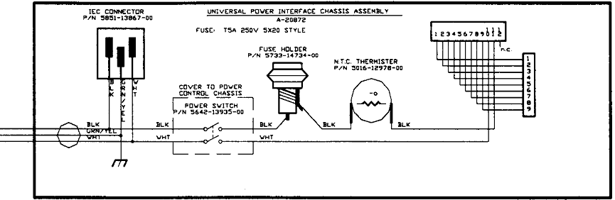
The original schematics. At the left power comes from the wallplug (back of cabinet) into the metal box at the front right
in the cabinet.
The the wires are split off go power the service plug, and continue towards the on/off switch.
Behind that is a fuse and NTC, and further the plug to adjust the voltage and then exit the box towards the transformer.
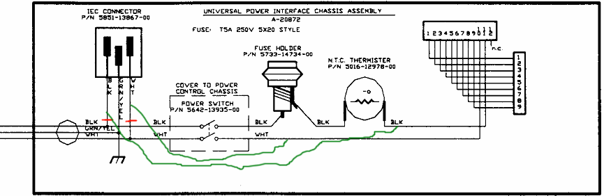
This is the modified circuit. Red lines is where we cut, green is how the service plug will be connected now.
Totally in the end, before power leaves the box, even after the NTC and fuse.
You could also plug in between the on/off switch and the fuse, if you don't want fused protection on what you'll connect.
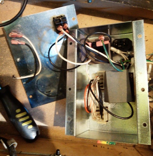
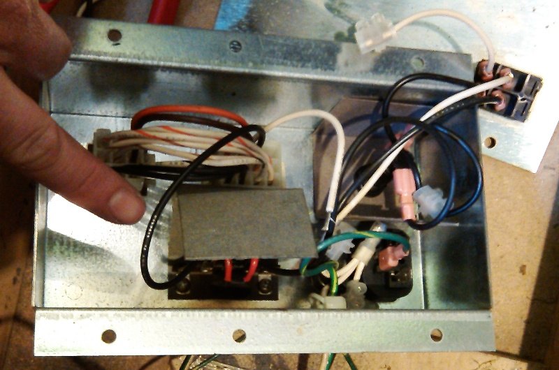
The opened box. At the left in the lid is the on/off switch. Top right is the service plug.
Below underneath the cardboard is the NTC and fuse holder. Left the wiring to set the power level.
Links ervan de pluggen om het voltage in te stellen.
The black and white wires that went to the service plug have already been
cut and shown on the left side. I will re-use them.
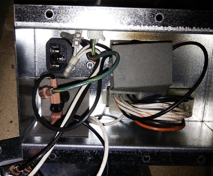
Normally the black and wires each come together with 3 inside the plastic housing.
There I've cut the wires going towards the service plug. The cut parts I've insulated with a plug so they can't short anything.
We'll cut the black wire going from the NTC towards the large plug and split off from there with our wire.
Same for the white wire going towards the same plug.

The whole circuit finishde. The previous cut wires are now split off further in the circuit, so the service plug
only gets power after the on/off switch.
If you're looking for pinball parts, then check out Pinballshop.nl (affiliate link).