
DIY Switch tester tool for WPC pinball machines
This tool appeared on eBay Germany some time ago. The listing described it as a switch matrix test tool, developed by someone in Germany
who worked for a subsidiary of Nova, a major distributor of Williams pinball machines in Germany. It eventually sold for 57 euros.
57 euro for a small PCB? That’s quite a bit, especially considering the part doesn’t look very complex. It appears to be a printed circuit board with some connectors, but no active components.
When I sent the picture to Leon, he quickly analyzed it and
described how to make it yourself.
The concept behind it is actually quite clever.
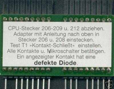
What the tool does is reverse the rows and columns in the switch matrix, effectively swapping the polarity of the diodes.
This means that when you're running the switch matrix test, any switch that functions correctly won’t register at all.
Only switches with faulty (open) diodes will show up during the test.
Switch matrix issues can originate from two places: the playfield wiring or the CPU board itself. If the problem lies within the CPU board, you can test it directly. But if the CPU board checks out and the issue persists, then the fault is somewhere in the playfield wiring. That’s where this tool becomes invaluable.
This isn’t a tool you’ll use frequently. Switch matrix problems, like when an entire row or column activates when you press a single switch, thankfully don’t occur often. But on the rare occasion you encounter a puzzling issue with the switch matrix that seems unsolvable, this tool can save you hours of troubleshooting.
Without it, you might spend countless hours tracing wires, desoldering connections, testing diodes... Most people dread diagnosing switch matrix problems, not because it’s technically difficult, but because it’s incredibly time-consuming. Some switches, especially the diodes attached to them, are notoriously hard to access.
Fortunately, building this tool yourself is straightforward. It simply plugs in between the CPU board and the connectors. The reason you can’t just swap connectors J206 and J208 on the CPU board is because they’re keyed differently. So, all this PCB does is reroute the connector from J206 to the pins of J208, and vice versa.
With just a few dollars’ worth of parts and about half an hour of soldering, you can easily make this tool yourself. It's not a tool for anyone, only when you often have to repair WPC pinball machines with weird switch issues, this tool will be a huge timesaver.
If you're looking for pinball parts, then check out Pinballshop.nl (affiliate link).