
How to diagnose and repair ball through problems
If your pinball machine gives out too many balls at the start of a new game, here is the solution. This article describes how to diagnose and repair ball through problems on pinball machines. It deals especially with the 6-ball opto ball through pcb as a lot of games have problems with this, but the testing principles can be applied to other ball throughs and regular opto detectors too.
Williams / Bally produced a few games that use 6 pinballs: Popeye, Star Trek The Next Generation, Indiana Jones, Demolition Man and Judge Dredd. To accommodate 6 pinballs in the ball through, Williams designed a new set of opto boards that are large enough, part numbers A-17981 and A-17982.
Unfortunately there was a design problem with these boards: the resistors on them run too hot. This causes damage to the board. The resistors can even unsolder themselves , or the pcb has burn damage and needs to be 'hacked' to continue to work.
If you have any of these pinball machines and it gives you 2 pinballs at startup, you probably have a problem with this board.
As shown in the pictures, new designed repro boards are available. These are plug and play and will fix the multiball problem, and are more resistant to the problem. The original boards are also still for sale, and while they work fine for home use, it is better not to use these anymore when the pinball machine is still operated and is switched on for many hours every day.
Instead of buying new pcbs, it is better to first troubleshoot the problem, identify what opto is burnt, and check if it still can be fixed.. the new pcb's aren't cheap and the old ones can sometimes be repaired without a problem, depending on how bad they look.
The way these boards work is not very complicated. On each side of the ball through is an opto board. One side (the side on the playfield) contains infrared (IR) receivers. The other side (closest to the coin door) has IR-emitters on it. These IR-emitters are leds that emit infrared light, a small light beam shines trough the ball through (where the balls rest in) into the receivers on the other side. If there is a pinball in the ball through, it will interrupt the infrared beam. The receiver does not see any IR light, and this switch will be 'closed' in the switch matrix test.
Infrared receivers almost never go bad. The IR transmittors however do go bad, or have problems with the resistors on this 6-ball pcb. When they are bad, the game thinks there is a pinball blocking the IR-beam, and thus tries to kick out an additional ball when a game starts.
How do we test these pcbs ?
1. Check the receivers. Although they almost never go bad, it's possible.
Remove all pinballs out of the game.
Remove the opto emitter board (closest to the coin door) from the assembly.
Go into the switch test mode of the game.
Shine with a flashlight (that has a real bulb, not a led !) trough each of the holes in the metal ball through, into the ir-receiver
on the pcb at the other side. These receivers look like a very dark led.
They must detect the light beam and the switch will react in the switch test.
Double check the number and description on the display that it is the correct switch detected.
If all receiver leds work then the problem is probably with the emitters
2. Check the emitters. Here you probably will find a problem.
You can not see infrared light with the naked eye, but the preview screen of a digital camera can.
So the easiest way to check if all ir-leds work, is to remove the pcb from the ball through
(was done in the previous step). Keep this pcb plugged in and switch on the game.
All ir-leds should light up. View the pcb trough your digital camera and you should see
each purple led emit light. If there is one (or more) that does not emit light, it's broken.
Either the ir-led needs to be replaced, or the resistor associated with it is bad.
Mark what led does not shine, remove the pcb from the game, and inspect it. Using your dmm you can measure continuity to check there are no broken traces, everything is still soldered correctly, the resistors are not shorted, ...
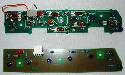
An original pcb on top, a repro at the bottom.
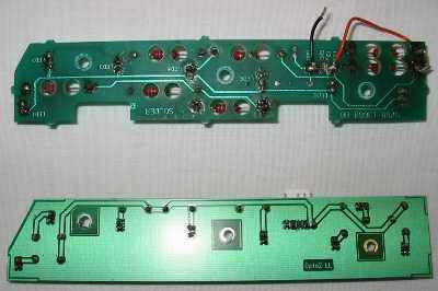
Reverse side of original and repro pcb.
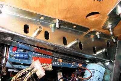
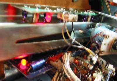
Emitter pcb is removed from the ball through. trough the holes in the metal, the IR beam shines
into the IR-receivers.
If you go now into the switch test, you can shine with a flashlight into each receiver and it must detect this.
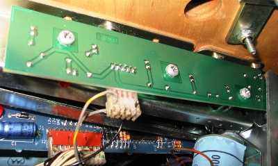
Repro pcb installed.
Pinballs will rest into the V-shaped groove and block the infrared beam.
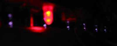
You can not see the infrared beam with your eyes. However, if you look at the preview window
of a digital camera, or take a picture, you will see the purple ir-leds light up.
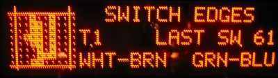
The switch matrix test shown on the dmd. All opto switches should be open when there is no
pinball installed. A pinball rolling down will activate the switches one by
one, as it rolls down it will block each infrared beam.
Photos by Michel O.
If you're looking for pinball parts, then check out Pinballshop.nl (affiliate link).