
IC and connector pin numbering
When reading schematics or following repair guides, you'll often encounter references to pin numbers on ICs or connectors. So how do you easily locate the correct pin? And how do you properly replace an IC or EPROM in a socket?
Fortunately, pin numbering follows a universal standard in the electronics world.
IC pins are numbered counterclockwise
Pin 1, where you begin counting, is typically marked on the IC. This marking can appear in various forms: a physical indentation, a printed dot, or a notch. Once you've identified this mark, count the pins in a counterclockwise direction.
Pin 1 (or the side where to start counting) is normally indicated on the IC.
How it is visually presented can have many forms - a physical indentation, or it can be a printed mark.

Find pin 1.
When replacing chips (ICs or EPROMs), always locate the indentation to identify pin 1. Never rely on labels or printed text to determine the orientation of the chip. These can be misleading.
 In the image , all ICs are oriented the same way: pin 1 is always at the bottom left. This demonstrates the different ways pin 1 can be indicated and which indentations matter.
- The LM339N IC at the top right shows the most straightforward method: an indentation on the short side with no other markings. Start counting counterclockwise from this notch.
- The two ICs on the left are similar: only the small edge indentation counts. Ignore any other indentations on the top surface.
- The IC at the bottom right is unique. It lacks side indentations but features a printed white square to mark pin 1. Disregard the nearby round indentation.
On boards, pin 1 of a connector is indicated
There’s no strict universal rule for connector pin numbering, it often depends on the board designer. To be safe, always look for printed indicators on the PCB itself.
As a general rule of thumb: connector pins are usually numbered clockwise around the board. This convention is followed on Bally/Williams WPC games and Data East machines. Even the connector labels (J1, J2, J3, etc.) tend to follow a clockwise pattern.
However, exceptions do exist. Sometimes connectors are added later, breaking the numbering pattern. Designers may also choose their own conventions.
Connector pin numbering on Bally/Williams pinball machines
Connector pins are numbered clockwise, easy to remember, right? But explaining it in words can be tricky, so refer to the image for clarity.
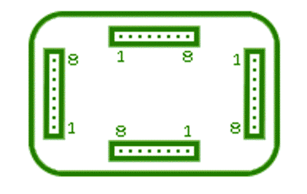
- Start at the top edge of the board and count pins from left to right.
- On the right side, count pins from top to bottom.
- At the bottom and left sides, the numbering is reversed: right to left and bottom to top.
The bottom edge often causes confusion, as most people are used to reading left to right. Counting pins from right to left isn’t intuitive. I’ve seen errors where GI connectors on the bottom left of the board were rebuilt with wires in the wrong order.
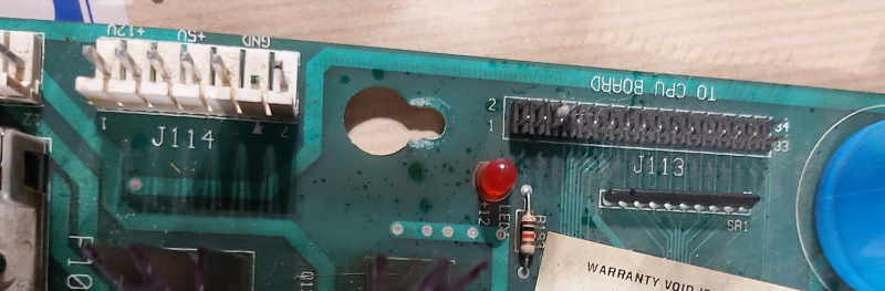
Note how pin 1 and pin 7 are printed for connector J114. The J113 flat cable connector also has pins 1, 2, and the last pins clearly marked.
Positive and Negative side of electronic parts.
For some electronic parts, it doesn't matter how they are soldered in. An example are radial capacitors: these are capacitors that have a solder leg on each side: one on top and one on the bottom.
Other electronic parts such as axial capacitors (that have 2 wires on the bottom) and leds, have a positive and negative side. In documentation, the positive side is called the Anode and the negative side is called the Cathode.
On axial capacitors, usually the negative side is indicated. As you can see in the picture below, there's a negative sign, but sometimes it's just a colored band to indicate the negative side. Even if there is no indication at all, the component can still be polarised. Check the length of both legs and if they are different, then the shorter leg is normally the cathode (negative) side.

On capacitors usually the negative side is indicated.
On the small capacitor on the right, the negative side also has a shorter leg.
LEDs are also polarised and you can also tell the difference in the leg length. The longer leg is positive (Anode), the shorter leg is the negative side (Cathode).

There's a small difference in leg length, and it matters.
If you're looking for pinball parts, then check out Pinballshop.nl (affiliate link).