How does the switch matrix in a pinball machine work
A pinball machine has to know where the ball is so it can interact with it and score points.
This is done using switches. The pinball rolls over or hits a switch, which is connected to the cpu. The cpu registers this
hit and can take whatever action it needs to do to respond: add points, activating a solenoid, play a sound or animation, and much more.
As an example the switch matrix on Bally / Williams WPC games (dot matrix games from 1990-1999) is used, but the same principles and theory is valid on all other types of electronic pinball machines. Only on older, electro-mechanical pinball machines every switch is connected by itself to a relay.
Different types of switches
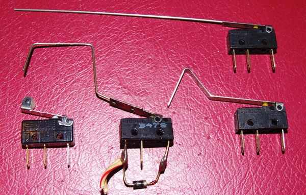
There are many types of switches used on a pinball machine: regular leaf switches, microswitches,
optical switches and magnetic (reed switches and eddy sensors). More information about how they work
and how to adjust them can be found in this article about adjusting switches.
It doesn't matter what type of switch they are, when they are connected to the switch matrix
(sometimes using a special board, like for opto switches) they act the same.
What is the switch matrix
The switch matrix is the way switches are connected in an electronic pinball machine, and how the computer knows what switch exactly is
activated. Each switch is connected by 2 wires. There are no 2 individual wires that run from each switch to the backbox.
On a game with 64 switches, this would result in 64 x 2 = 128 wires. That would be too much to connect.
To simplify things, only 16 wires are used. The switches are organised in a (virtual) grid (or matrix), with rows and columns.
Only 16 wires are used: 8 for the rows and 8 for the columns.
History of the switch matrix
The transition from electro-mechanical components to solid state (computers) suddenly gave a pinball designers lot of extra
power to process and control more things on the playfield. Adding rules on electro-mechanical pinball machines was limited by physical constraints.
It meant adding more wires and relays to the bottom of the pinball cabinet. There was only a limited amount of space
available, and adding more parts also meant more expensive machines to produce.
Suddenly this all changed - there was a large amount of memory and processing power available. More rules didn't
imply extra costs, as long as the designer stayed within the limitations the system was designed for.
This change allowed game designers to make more complex games.
Using two separate wires to each switch - one to provide power to all and one that goes immediately back to the cpu, would limit
the number of switches. Having 8 input lines would mean only 8 switches could be read. More switches meant many more connectors
and miles more of electrical wire, and would probably slow down the cpu too much.
To keep the wiring still under control, a switch matrix was implemented on pinball machines with electronic boards.
Connecting all switches in a matrix was the solution. Switches are not wired individually, but wired in a grid (matrix) with rows and columns.
A smaller amount of inputs and outputs can now be used to read a large amount of switches. The first generation of electronic pinball machines
(Bally, Stern, Gottlieb System 1) used a 5 by 8 matrix, allowing for 40 switches.
More recent games use an 8 by 8 switch matrix,
giving pinball game designers the option to read status of 64 switches (and this number sometimes isn't enough). All this using only
8 inputs and 8 outputs on the cpu board, keeping resources (wires, ics, ..) to a minimum.
How the switch matrix works
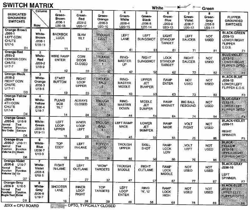
The manual of a WPC game shows the switch matrix, switches are nicely ordered in rows and columns and the wire colors are documented.

Cirqus Voltaire pinball machine switch matrix,
as documented in the manual of the game.
The picture above shows the switch matrix for the Cirqus Voltaire pinball machine. Ignore for a moment the far left and far right columns
(dedicated ground switches and flipper grounded switches) as these are not part of the matrix.
What you see in the middle is the 8 by 8 switch matrix. At the top the 8 columns are listed, these all have a green wire,
marked with an additional colored stripe (brown, red, orange, ..) to identify between them.
Eight rows are also listed, these have white wires (with an additional color stripe).
It is important to grasp this concept. Both wires on a specific switch will not continu both further to the same next switch, and so on.
They will also not immediately return to the cpu-board.
Each wire is daisy-chained towards another switch, either in the same row or the same colunm, depending on what type of wire it is.
As an example, the white-brown wire of row 1 will first go to the backbox luck switch (number 11). Then it will go to the slam tilt switch
(21), through eject switch (31), and so on.
The column wire (green-brown) that also starts at the backbox luck switch (11),
continues to another set of switches in that column: wire ramp enter (12), start button (13), .. and never connects again to any of the
other switches the white-brown row wire goes to. Each switch is connected by an unique combination of row and column wires, that
define what his location in the switch matrix is.
When you are troubleshooting switches, looking for a broken wire or other fault, it is important to always look at this switch matrix chart to know where exactly each wire on a switch lug comes from and goes to next. Without this chart, if you just try to follow wires underneath a playfield, it will make things very difficult and waste a lot of time.. Therefor you should never try to attempt complicated troubleshooting if you do not have the game specific manual.
Now how does the cpu read the status of these switches ? It scans them - very quickly one by one. The cpu turns on 1 column and read the status
of the rows.
Let's continue our example. Say the cpu turns on column 2. Columns are hookup up to an output channel on the cpu board.
Electricity flows through the wire (starting at the top in the column in the matrix). When one or more switches in that column are closed,
this means a contact is made and the electricity will return now on the row wire. This continues to left.
The rows are connected to input channels on the cpu, so it knows on what row the signal returns.
Now the cpu nows what rows on that column are closed. Power to that row is turned off, and the next column is
activated. This happens very fast: multiple times per second, so fast that no closures are missed and it looks for a player
as if each switch is being read simultaneous.
Diodes in the switch matrix
Electricity flows in all directions. Why does only the closed switch get reported, when all rows and columns
are connected to eachother ?
That's what a diode is for.
In the schematic on the top right of the picture above it's illustrated as ->|-
A diode is a small electronic component that allows current to flow through it in one direction, but blocks it into the other direction.
Electricity is allowed to flow into the direction of the arrow, but is blocked in the other direction.
The component looks like a small black tube. The silver stripe indicates the side that blocks electricity from passing.

Bottom center microswitch
has a diode attach between two of its lugs.
Because each switch has a diode, it is isolated from the other switches.
The blocking diode is very important. It must be present on a switch (some older Bally and Stern games did not use them
on certain cabinet switches), and hooked up correct. A lot of problems happen because of broken,
shorted or reversed diodes. When you replace a switch, always double check you connect it correct.

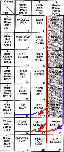
Cirqus Voltaire pinball machine switch matrix
The above picture shows how the cpu reads the status of switches in the matrix. To keep the drawing simplified,
I have only drawn diodes and path (wires) for switch 26, 27 and 37. Red = current, blue = wire without current.
In this example, switch 27 is closed, all other switches are open.
When column 2 is activated by the cpu, current flows down the column (red line, which is physically the green-red wire).
All switches in the column up to 26 are open. No current can continue over them to the rows and back to the cpu.
Switch 27 is closed, it is pushed in. The electronic path is completed, current can flow from the column to the row.
The current flows through the diode, through the closed switch, onto row 7 (physically the white-violet wire), which returns the electornic signal to the cpu.
The cpu gets this input and knows switch 27 is closed, as it activated column 2 and current returned at row 7.
If another switch was closed in the same row, it would know that the signal returns in 2 rows.
Note how the blocking diode on switch 37 works. A diode only lets electricity pass in one direction and blocks it in the other direction.
Switch 37 is also closed, but the blocking diode stops the signal stops (where the red line and blue triangle meet). Current cannot flow
back over the blue line onto column 3 or any other columns or rows.
Testing switches
To test switches we go into the menus, to the selftests for switches. All electronic pinball machines have this.
On older games it is simple, if you press a switch on the playfield then the associated number will be shown on the score displays.
Pinball machines with alpha-numeric displays will show the number and name of the switch.
WPC games have a more user-friendly screen. Use the service buttons to go to 'T.1 switch edges'.

T.1 Switch edges selftest.
On the dmd you see the visual representation of the switch matrix, similar to how it's documented in the manual.
Each switch is represented by a dot. Closed switches are indicated as a square (with open center).

Activating a switch in the
switch matrix selftest.
If you now push on a microswitch on the playfield so it closes, the cpu will register and indicate this on the screen.
In the picture above switch 27 is activated. The colors of the wires are also indicated to help you with troubleshooting
(in case you don't have a manual, you can use this and take notes).
While you are in this switch test (T.1), you can activate each switch. They should all register correct - and only the switch you close should be indicated.
If you don't know where all the switches are: consult the manual. Every game (even the old first generation of electronic games have a page indicating the switch layout. It's a drawing of the playfield where all switches and their numbers are indicated.
What problems you can experience with switches and how to troubleshoot them, that's for another article.
If you're looking for pinball parts, then check out Pinballshop.nl (affiliate link).
