
Replace the led dmd in your Stern pinball machine with a real plasma dmd
This is a simple "how-to" guide for anyone that may wish to convert their Stern red LED display to a standard orange plasma display. I never really liked the red display that Stern uses in their games, more so because of the individual 8x8 block patterns that can be seen in the display. But, once my red LED display had it's first issue, only after 2 months of ownership, I wondered if a standard orange plasma display could be made to work in these games. This conversion was done on a Metallica PRO that was built on 9-5-2013. Since Stern seems to have stopped using plasma displays in their games, there will come a point at which they will no longer support the plasma displays and this conversion will no longer be possible.
My red Stern LED display with a constant
line on at the right side of the display.
So the first thing I needed to determine was if there was a way to get the voltages needed to run a plasma display. A look at the transformer diagram in the manual shows the following diagram below. As can be seen, there are several winding taps that are used to bring different voltages out for audio, controlled lamps, coils, logic power and display power. The lowest one labeled TO DISPLAY POWER SUPPLY PC BOARD is what we are interested in...if it still exists. What is shown in this diagram are all the pins inside the (15) pin connector that is connected to the output of the transformer. There are two more connectors on the secondary of the transformer that handle the fluorescent tube in the back box (blue wires) and all the games GI lamps (yellow wires). These are not shown in the diagram below. The bottom winding in the transformer is what we are interested in. This winding is what we need to have available to get the high voltages to run the display.
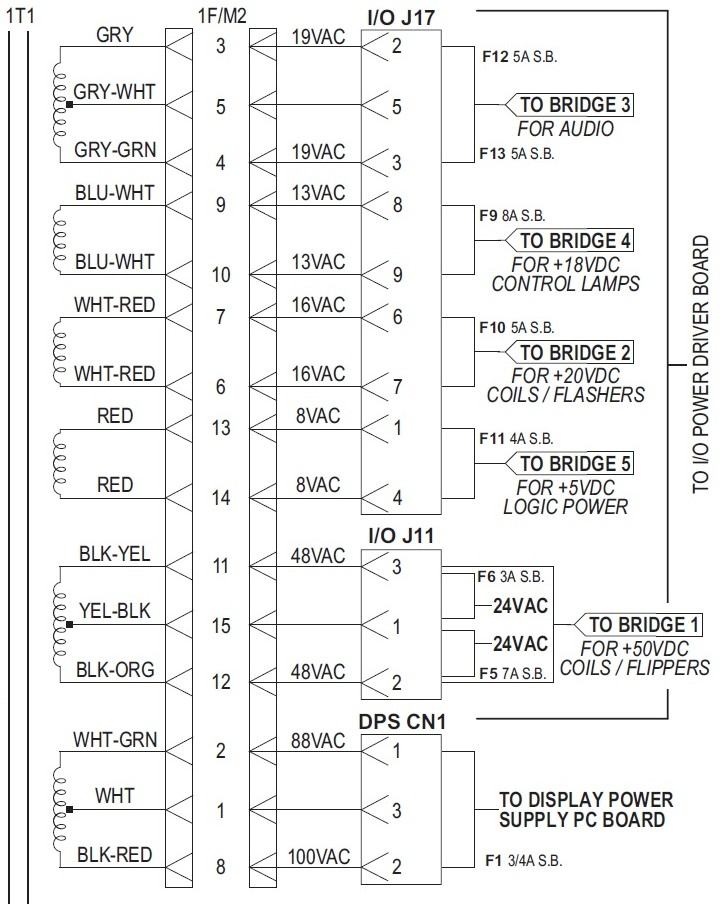
The diagram of the 15 pin connector at the output of the transformer. We are interested in the TO DISPLAY POWER SUPPLY PC BOARD connections.
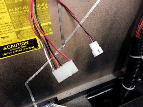
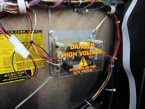
In the picture below, we can see see the three connectors in the bottom of the cabinet. The transformer is on the left side of the image. The connector towards the left, with the yellow wires, is for the GI lighting. The large connector in the center is the (15) pin connector that supplies all the voltages used to operate the game. The smaller connector, on the right with the blue wires, is to supply 120V to the ballast for the fluorescent tube in the backbox. We will be working with the large (15) pin connector in the image below.
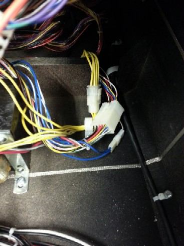
The three transformer output connectors located in the bottom of the cabinet.
So what we need to do now is determine if the wires, from the output of the transformer, are there to run the display. I disconnected that big (15) pin connector in the bottom of the cabinet. Below is the image of the connector half that is on the transformer side of that big connector. As we can see, all 15 positions are connected and wired up (luckily). This tells us that Stern's transformer still has the separate winding for the display and that it's wired up and connected to this side of the connector. Looking back up at the wiring diagram, This is labeled as connector 1F/M2. The pins associated with the voltages of the bottom winding are 2, 1 and 8. Pin #1 below is at the bottom right of that connector and if you look closely it's the only MALE pin there. Pin #2 is just to the left of pin #1 and pin #8 is the center of the middle row. Pins #2 and #8 are both FEMALE pins on this half of the connector.
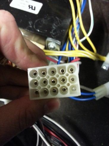
The transformer side of the large 15 pin connector in the bottom of the cabinet.
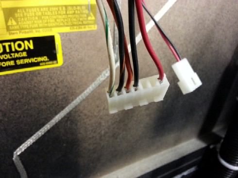
Below is an image of the other half of that same (15) pin connector. This is the half that has the pins and wires that go up into the game CPU and driver boards. This image is showing the back side of the connector so it's displayed in the same orientation as the other half. What can be seen in this image is that there are three wires missing. These missing wires are at pins #1, #2 and #8. So, it's safe to assume that Stern still uses the same transformer and connectors as the older plasma display games, they have just simply not run the wiring from the game side of that connector up into the game. So, we will need to add that back in. So looking back up at the wiring diagram again, the wire colors are pin #1 (white), pin #2 (white/green) and pin #8 (black/red). The pins used in this connector are sized at .093". So we are going to need some .093" pins and some wire. Remember that pin #1 was different on the other half of this connector.
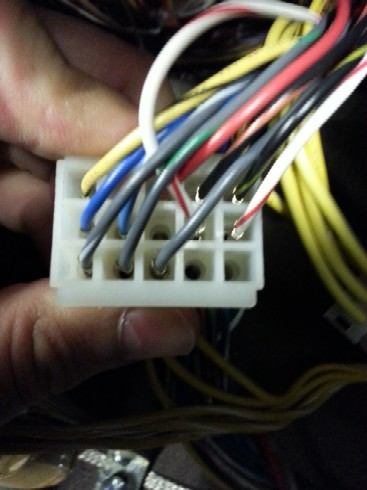
The game side of the 15 pin connector with wires missing at positions #1, #2 and #8.
Below I have gathered everything to do this project. I will discuss later what the other parts and pieces, shown here, are used for. But for now they are (clockwise from the top): (3) 6-foot lengths of 20 gauge wire. New plasma display. HV board mounting screws, .093" pins and connector. Stern HV display board with output cable attached. In the center are .156" connector and housing.
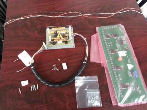
The parts needed to do this plasma display conversion.
The first step is to add the (3) wires back into that large (15) pin connector in the bottom of the cabinet. Luckily I had an old wiring harness from a parted out game and was able to source out the the white/green and black/red wires. Unfortunately I had no white wire long enough so I decided to substitute orange. So throughout this write-up the orange will be used in place of the white. If you want to source the correct wire, Bay Area Amusements (BAA) carries the correct color coded wiring on their site. They sell them in 10-foot lengths; so you will have plenty. I would recommend either 18 or 20 gauge wire for this. You will also need a smaller length (12") of black wire and a smaller length (12") or red wire as well as described later on. So, below I have stripped and attached the .093" connectors to one end of the three lengths of wire using a pair of crimpers. Keep in mind that the wire that goes into pin #1 (white wire) needs to be a FEMALE connector and the other two that go into pins #2 (white/green) and #8 (black/red) both need to be MALE connectors. Great Plains Electronics (GPE) carries these .093" connectors. I will have a bill of material at the end of this write-up with part numbers so everything is in one place.
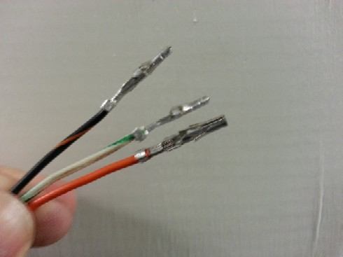
The three wires stripped and .093" connectors added. The white wire (orange in this picture) is the wire that has the female connector.
All that we need to do now is simply insert the pins into the connector housing as shown. The white wire (orange in the picture below) goes into the lower right position at pin #1. The green/white wire goes into the connector housing at pin #2 just to the left of pin #1. And the black/red wires goes into the connector housing at pin #8 located in the middle of the second row. Be sure to push the connector all the way in until an audible "click" can be heard. Also, because these pins have locking barbs on the sides, once you lock them in, they will require a special extractor tool to remove them. So be sure you have the wires in the correct positions before you lock them in. Especially the reversed pin connector at position #1.

The 15 pin connector with the 3 wires installed at positions #1, #2 and #8.
Below I have removed the translite and laid the speaker/display panel on the cabinet. The green LED display is at the bottom. This display has two connections. The ribbon cable that sends the data to the display and one that supplies 5V to the display to operate the LEDs. The 5V connector is the one on the right in this picture in front of the yellow sticker. It uses both black and red wires. The other connector in front of the yellow sticker with the red wires is for the speakers. We won't be touching the speaker connector, but we will be getting to the 5V connector as part of this conversion.
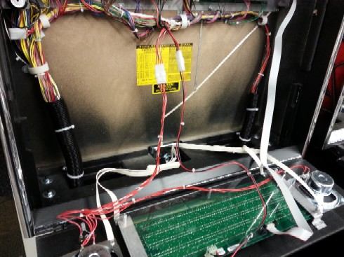
Inside the backbox showing the LED display and 5V connector (right).
Thread the other end of the three wires from the (15) pin connector in the cabinet up into the head and inside the plastic loops to get them in the vicinity of the two connectors (speaker and 5V) in the center of the backbox. You can adjust the positioning later, but below you can see the three wires we added dangling with the 5V connector disconnected.
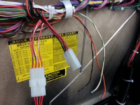
The three wires from the 15 pin connector run into the backbox and the 5V connector disconnected.
The next step is to tap into the 5V connector in the backbox. The 5V will be used for the plasma display as well. I didn't want to compromise the 5V connector that is attached to the LED display in case someday I wanted to put the LED display back in. So I made up a new 5V connector as shown below. These are .093" sized pins and connector housing like what was used in the cabinet, but this is only a 2-position connector. The wiring is one red wire and one black wire. Again, BAA has these wires as well, but these are just 12" lengths of #18 or #20 gauge wire. Both connector pins used here are MALE .093" and (1) 2 position .093" connector. Again, I will have a bill of material with part numbers later.
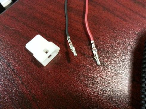
The 5V connector and wires already spliced and pinned.
Insert the pinned end of the wires into the connector housing with the black wire at the position closest to the point part of the connector and the red wire at the position closest to the flat, short side of the connector as shown below. Again, push the pins into the connector until an audible "click" is heard. As with the other connector, once these pins are locked in, they will be difficult to remove so be sure to install the into the correct positions in the connector.
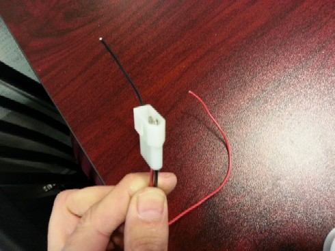
The red and black wires inserted into the 5V connector.
I guess you've been wondering what we are doing and why we are doing all of this. I figured this would be a good place to do so. In order to get the voltages necessary to run the plasma display. Shown below is the schematic of the High Voltage (HV) board we need to install to run the display. When Stern went to the LED display, they only needed 5V. The high voltages were no longer needed as well as the HV board needed to convert these high voltages the plasma display needs to operate. So Stern removed this board from the back box along with all the wiring. What we are concerned with mainly is the CN1 connector on the left side of this diagram. The (3) wires we ran earlier will be connected here. If we scroll back up to the the transformer schematic at the top of this page, we can see that the CN1 connector is shown to the right side of the lowest part of the diagram. You can see the CN1 connector shown there and corresponds to the connector shown below on the left side. The three wire we connected inside the (15) pin connector at pins #1, #2 and #8 will run up and connect to the HV board connector CN1 at pins #3, #1 and #2 respectively. The three wires we added will bring up 88VAC (white/green wire), 110VAC (black/red wire) and the transformer ground (white wire).
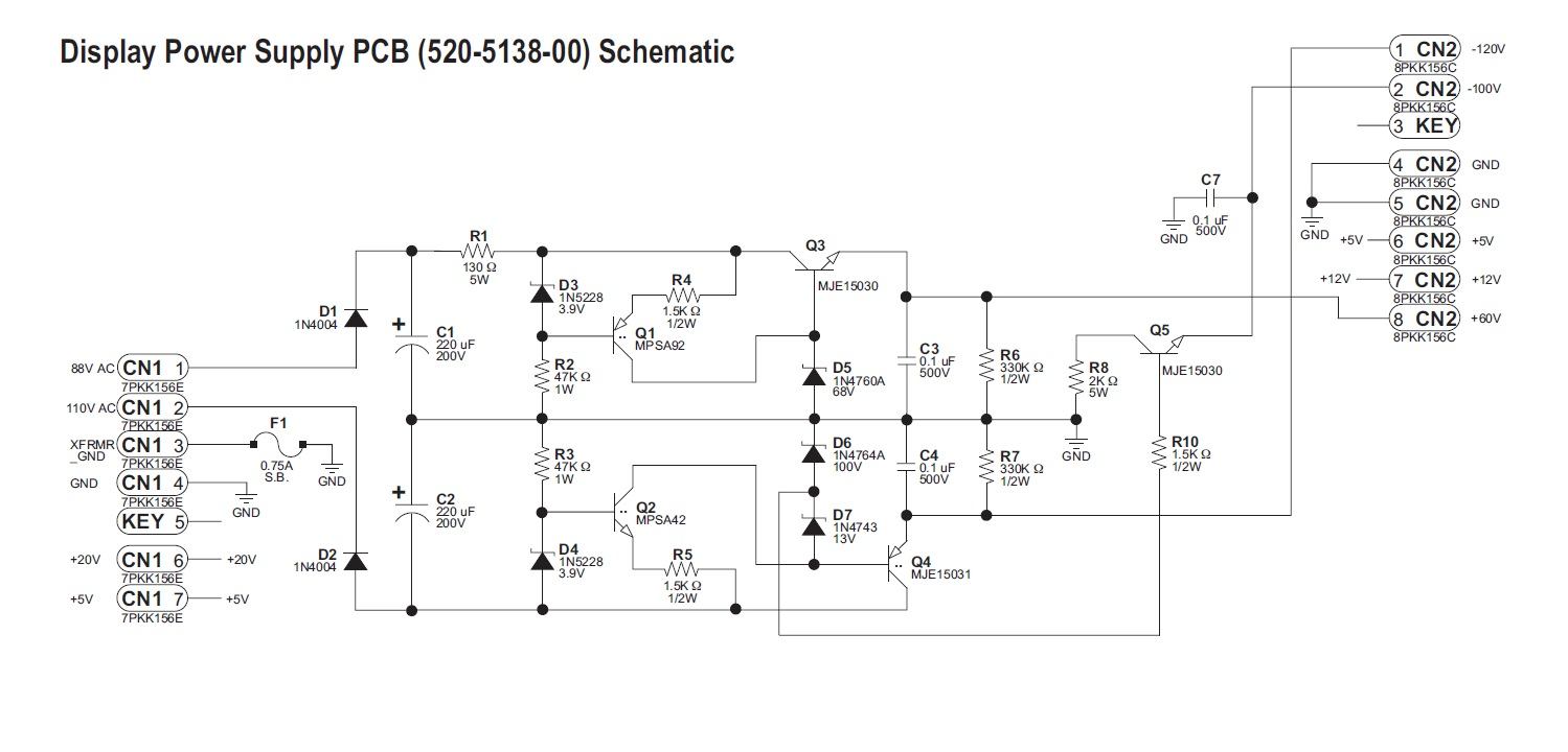
The schematic of the Stern HV display Power Supply board 520-5138-00.
Below is a components layout of the actual HV board. Please keep in mind that the header CN1 shown in the schematic above is reversed to what is shown below. Pin #1 is at the bottom of the board and pin #7 is at the top. The schematic above is correct, it's just pictorially not a representation of how the actual header is installed on the board.
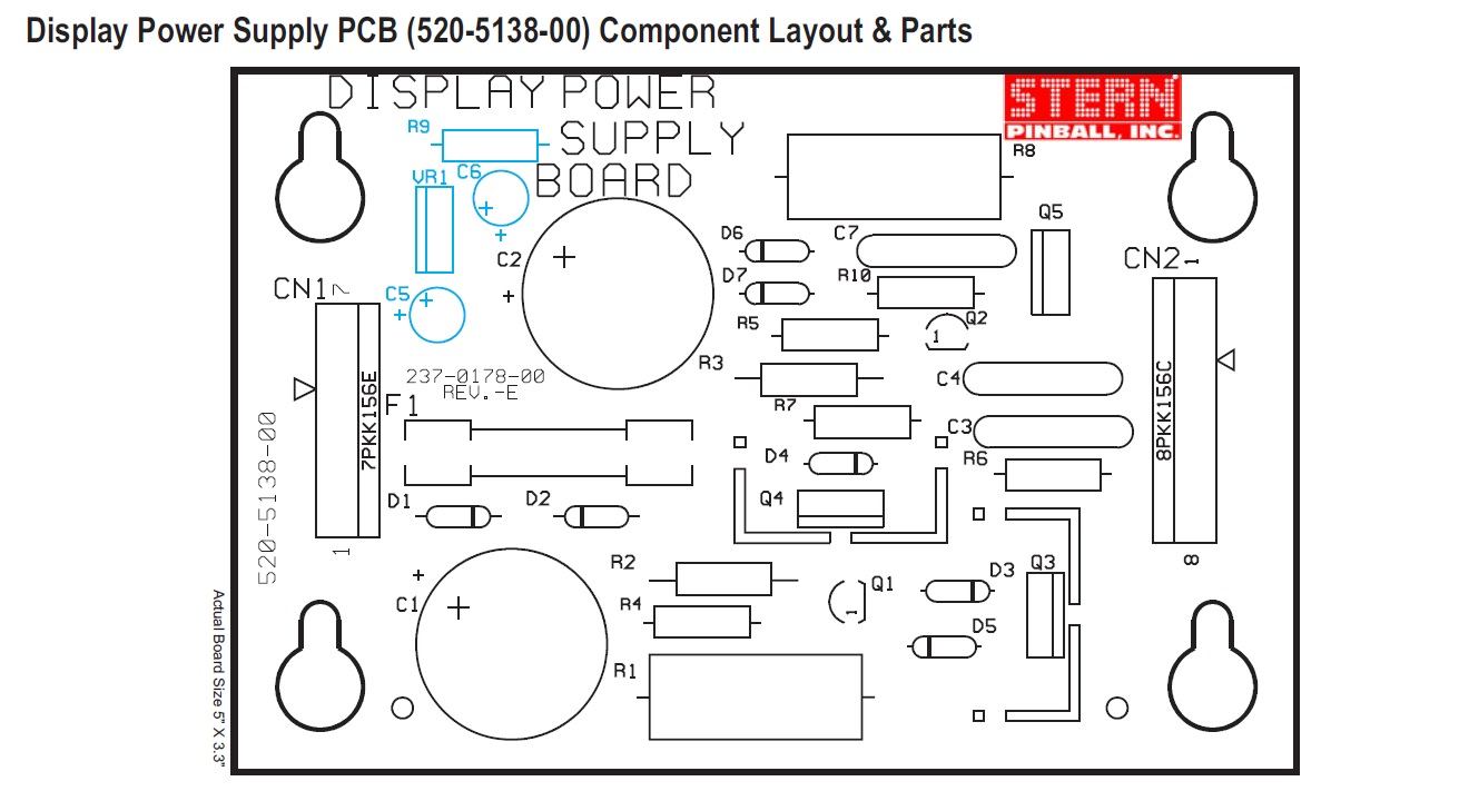
The component layout of the HV Power Supply board 520-5138-00
So what we need to do is create the connector that will plug into the HV board header connector CN1. What we need is a (7) position .156" connector housing, (5) .156" connector pins and (1) .156" keying plug. The connector housing may have locking ramps built into one side. So, determine what side that is and how that will interface onto the header on CN1 of the HV board. This will determine which opening is pin #1 and which is pin #7. Insert the keying plug into the opening that will line up with position #5 on HV board. Strip the ends of the (5) wires (white, white/green, black/red, red, and black) and crimp a .156" connector pin onto the end of each. The white/green wires goes into position #1 of the connector. The black/red wire goes into position #2. The white wire goes into position #3. The black wire from our 5V connector goes into position #4. Position #5 is the keying plug and position #6 is left open; so no wire goes there. Lastly, the red wire from our 5V connector goes into position #7. These .156" connector pins go into the housing a certain way so they can lock in. They can be difficult to remove one clocked in. Also, if you insert them upside down, removing them will damage them and you'll have to cut it off and put another on one, so get a few more that what you need, just in case. The diagram below shows our 5V connector we made up on the right with its wires running into the new .156" connector on the left. The .156" connector shown on the left is shown with position #1 on the left and position #7 towards the right. The keying plug can be seen slightly protruding from the bottom of the connector at position #5.
The newly made .156" connector that will plug into CN1 on the HV board.
Below is a closer picture of that .156" connector that will plug into CN1 on the HV board. The locking ramps can be better seen along the bottom edge of the connector. These will lock onto the header to help hold it to the board. So make sure the locking ramps are oriented correctly with position #1 and #7. The keying plug goes in position #5 next to the black wire and cannot be seen in this view below.
A close up view of the 7-position connector and 5V 2-position connector on the right.
Next we need to mount the HV board in the backbox. The HV board comes with (4) hex head screws and washers. This is the only part of this entire conversion that will require that screws be run into the backbox. Obviously this will leave holes once the HV board is ever removed. So if you don't want to do that, you may want to mount it differently. But you will then need to make sure that you attach the ground braid to the mounting plate somehow. I will leave that up to you. I mounted this HV board as Stern has done in their past games. The ground braid makes a 'Y' over on the right side of the backbox. Place the board so that three of the mounting holes are directly over the ground braid and run the screws through the center of the ground braid and securely into the backbox. The fourth hole (bottom right) will not go through a ground braid.
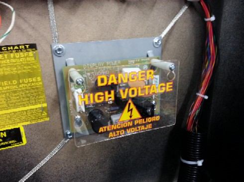
The Stern HV board installed in the backbox with the included hardware.
Below is the installed HV board. Install the new 7-position .156" connector we just made into the left side header connector CN1 of the HV board and plug in the 5V connector, we also made, as shown below. The output cable that goes to the display is already shown attached to the right side of the HV board in the picture below. This cable already comes attached.
The HV board installed and all connectors attached including the 5V connector.
Next we need to remove the LED display. Remove the 5V connector and the ribbon cable from the display. We will not need the 5V connector but we will need the ribbon cable. So store the 5V connector that is on the display with the display for future use.There are (8) hex head screws that hold the display mounting bracket to the speaker panel. There are two ground connections that are under 2 of the screws, so be sure to reconnect those. Once the display is removed, remove the red filter plastic and store with the LED display. The black masking will be reused. After some trial and error, I found that the plasma display viewing area is just ever so slightly larger than that of the LED display. Therefore you will need to cut 1/8" of an inch off the inside of the black masking on the left and right sides and 1/16" of an inch off the inside of the black masking at what will be at the top of the display. The bottom is fine to leave as is. This shouldn't cause any issues when it comes time to reinstall the LED display in the future.
The speaker panel shown with the LED display and red filter media removed.
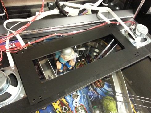
Below is the new plasma installed. Remove the brackets, standoffs, spacers, etc. from the LED display and transfer them over to the plasma display in exactly the same way. Note that the LED display has all the connectors at the top of the display and the plasma has all of its connectors at the bottom. So be sure to not install the display upside-down. The clear plastic protector can still be reused, just flip it over and reinstall. Below is the plasma display installed, ground wires hooked up, ribbon cable installed and the output cable from the right side of the HV board run to the display connector.

The plasma display installed with the HV connector and ribbon connectors installed.
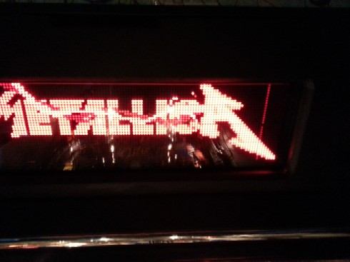
Go over your work one more time to make sure everything is connected up right and there are no tools in the cabinet or back box. Install the speaker panel and turn on your game. The display should now look like below.
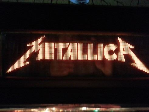
Metallica running on the plasma display.
Bill of Materials
(1) Plasma 128x32 display - This can be picked up from any of the online vendors. An older plasma you have kicking around may not work if it's at the end of its life.
(1) Complete HV board kit - This includes the HV board, mounting bracket, clear shield, mounting screws and output HV cable. You need to email or call Terry at Pinball Life as this is a special order part. He does carry just the HV board only as a standard part but does not come with all the other parts and pieces. Email or call Terry for pricing and availability of the complete kit. His website is: http://www.pinballlife.com/
(3) 6' lengths of #20 gauge wire (white/green, black/red, white) and (2) 12" lengths of wire (red, black) that can be purchased at Bay Area Amusements. Their website is: http://www.bayareaamusements.com/
The following can all be gathered from Ed at Great Plains Electronics. His website is: https://www.greatplainselectronics.com/
(1) 7 position .156" header #CS156-07-LR
(1) .156" keying plug #15-04-0219
(5) .156" #18-#20 gauge trifurcon connector pins #08-52-0113 (get a few extra just in case)
(1) 2-position .093" connector housing plug #03-09-2022
(1) female .093" #18 - #22 gauge connector pin #02-09-1119 (get a few extra just in case)
(4) male .093" #18 - #22 gauge connector pins #02-09-2118 (get a few extra just in case)
© 2013 Mike Schudel - reproduced with permission
If you're looking for pinball parts, then check out Pinballshop.nl (affiliate link).